
Introduction: The Core of Fluid Power Systems
A hydraulic valve is the “calculating” core of a fluid power system. While the pump generates raw flow, it is the valve that dictates direction, pressure, and flow rate, turning raw energy into safe, predictable mechanical motion.
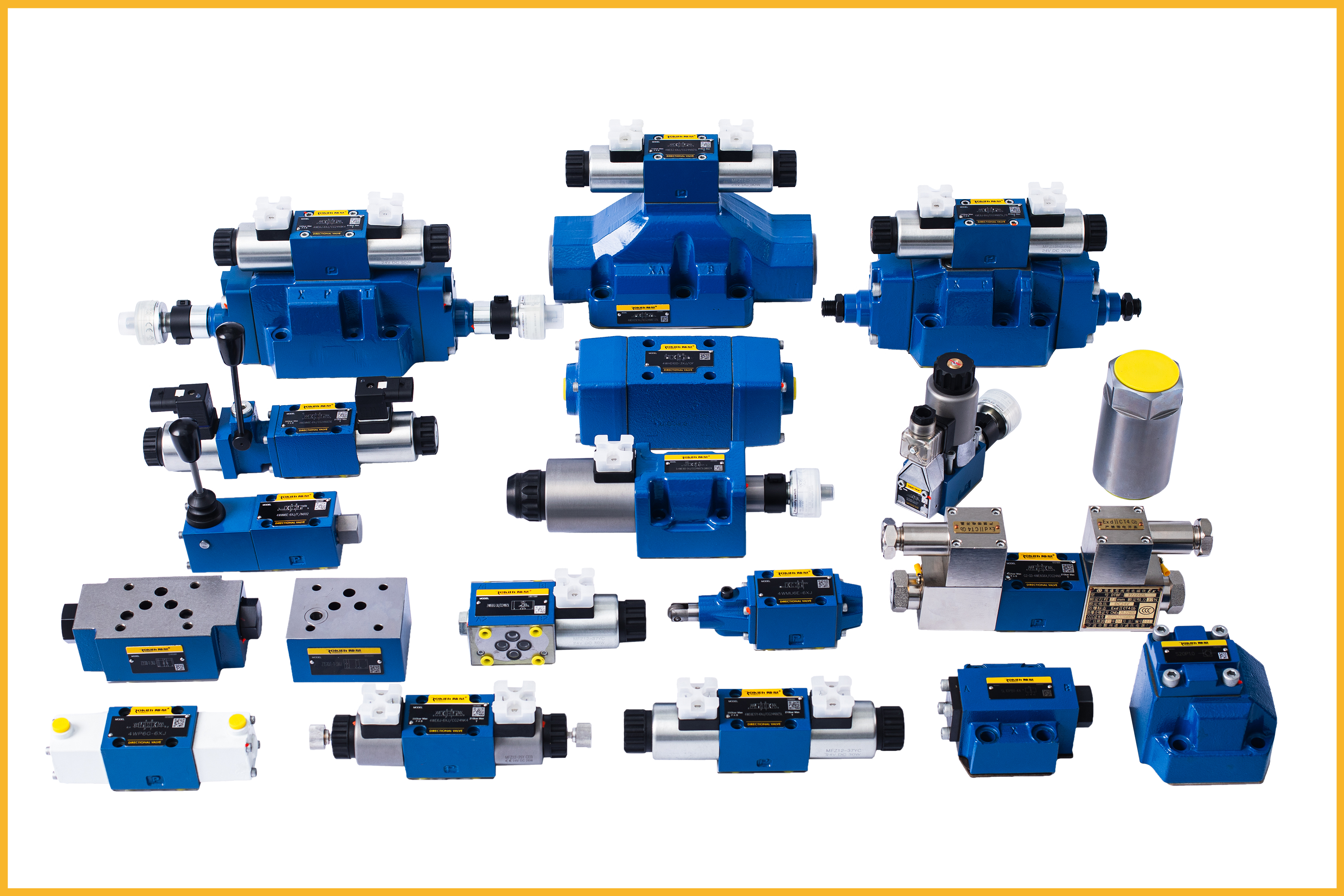
As a high-precision hydraulic valve manufacturer, we see that improper selection or a misunderstanding of valve dynamics remains the #1 cause of system failure worldwide. This guide provides an engineering-grade overview of how these components function and how to select the right one for high-stakes industrial applications.
What Is a Hydraulic Valve?
In technical terms, a hydraulic valve is a mechanical device designed to regulate fluid energy by opening, closing, or throttling internal flow passages.
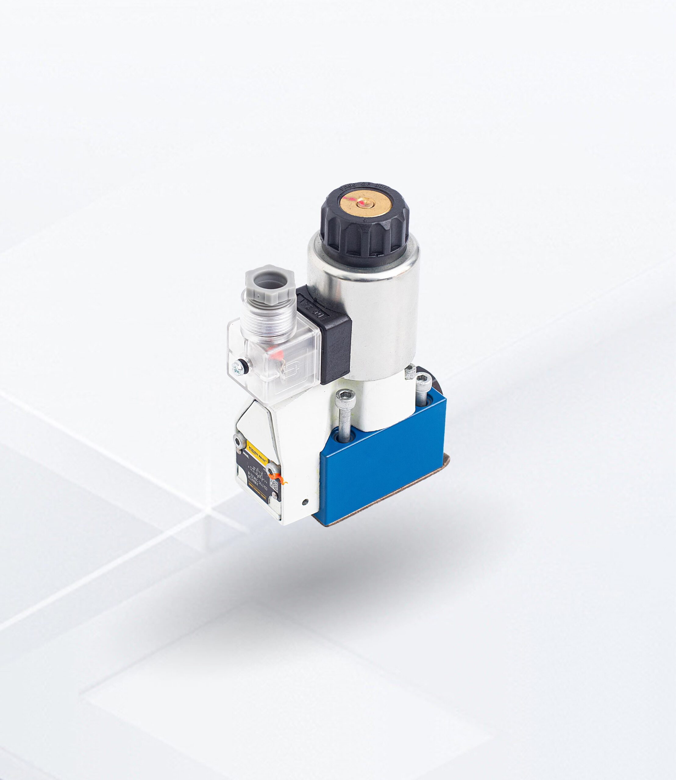
Unlike passive components like hoses, valves are active decision-makers. They respond to electrical signals, pressure differentials, or manual input to manage system behavior.
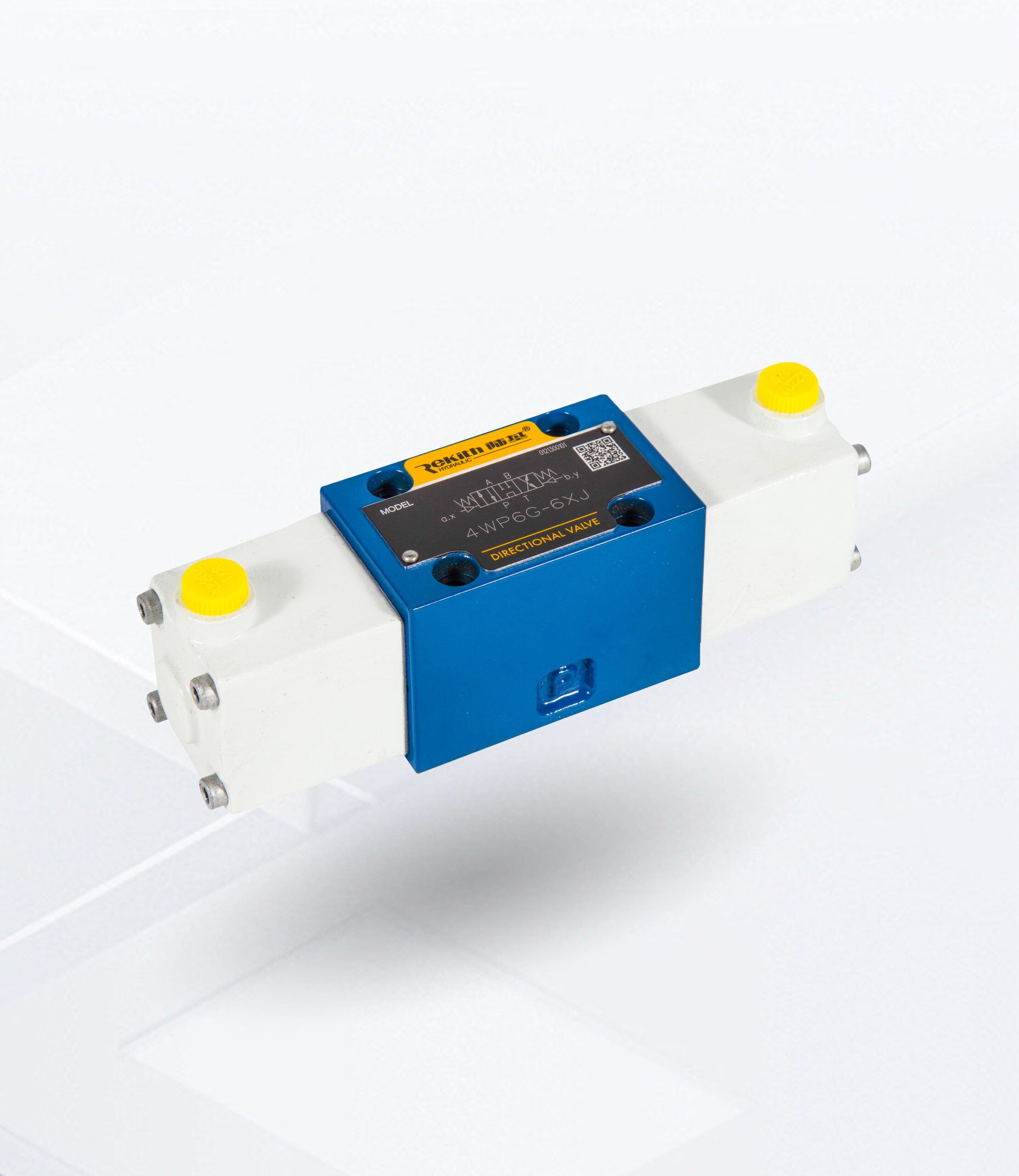
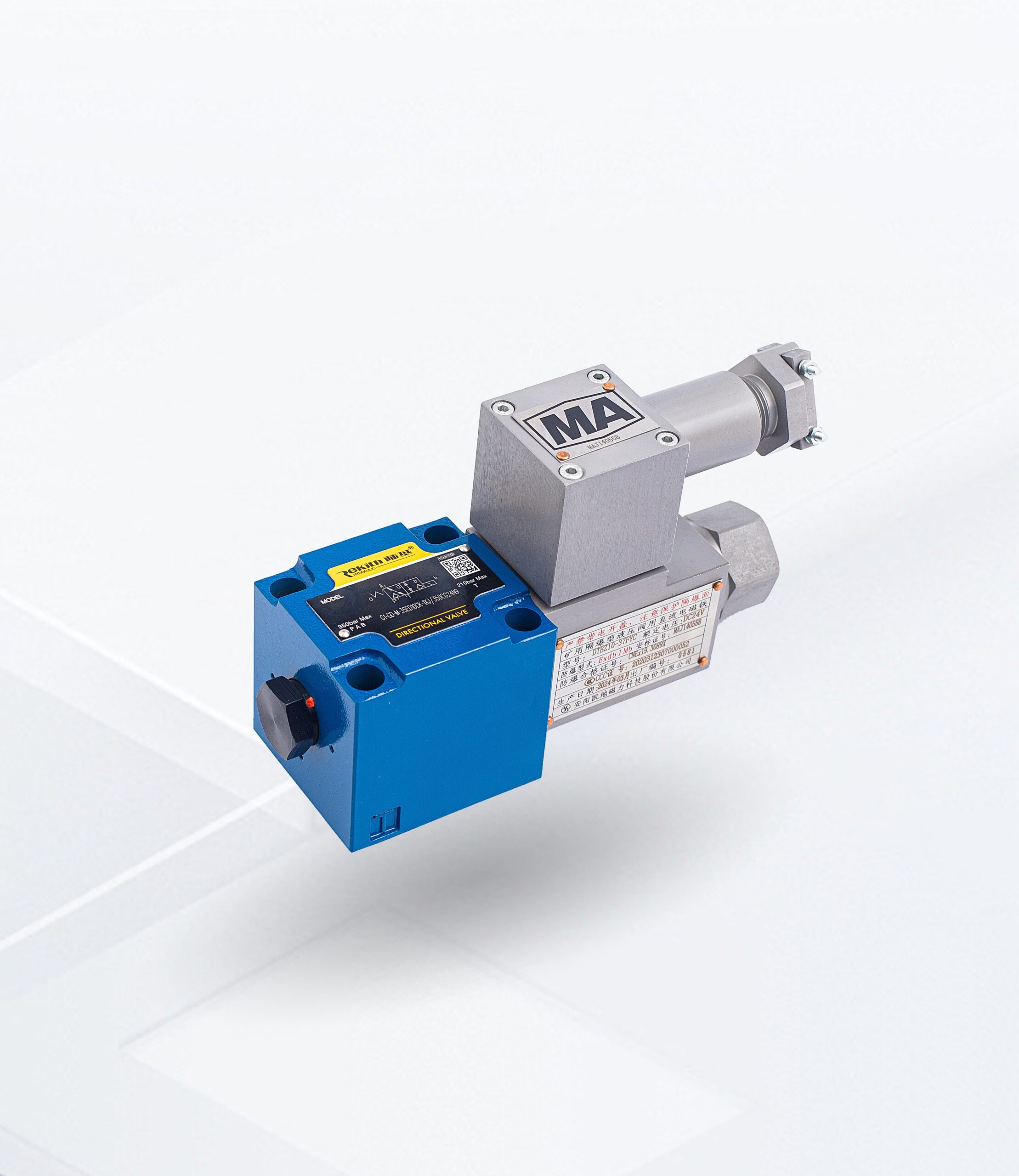
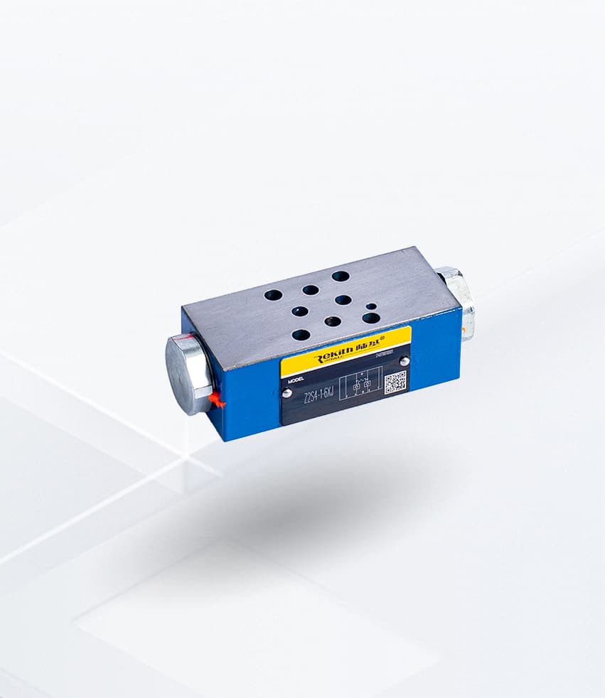
Material and Construction: At Rekith, we manufacture valve bodies from high-strength ductile iron or hardened steel alloys to withstand pressures exceeding 350 bar (5,000 psi) while maintaining zero-leakage performance in critical zones.
How It Works: The Physics of Precision
The core principle of a hydraulic valve is the manipulation of flow paths. Inside the valve body, a moveable internal component—typically a spool or a poppet—shifts position to align or block precisely machined channels.
The Micron-Level Challenge
For a valve to function effectively under high pressure, the internal geometry must be flawless. We adhere to the following strict manufacturing benchmarks:
-
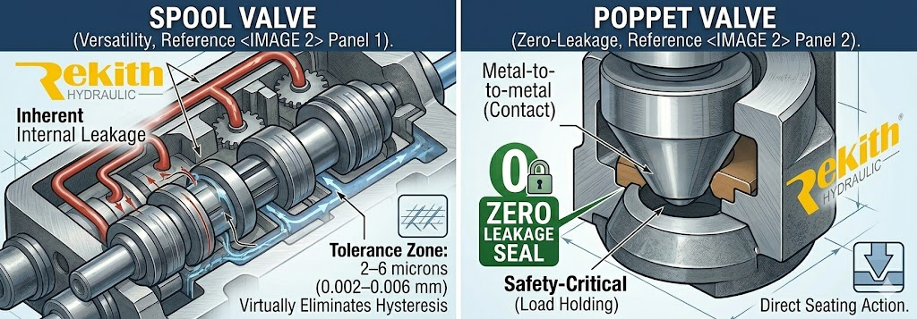
Precision Clearances: The radial clearance between the spool and the bore is maintained at 2–6 microns ($0.002–0.006$ mm) to balance responsiveness with minimal internal leakage.
-
Surface Hardness: Spools undergo advanced heat treatment to reach a hardness of 58–62 HRC.
-
Surface Finish: Sliding surfaces are ground to a mirror finish of Ra 0.2 μm.
Three Primary Functions of Hydraulic Valves
In fluid power systems, valves are categorized by the specific flow parameter they control. Understanding the distinction is the first step in system design.
-
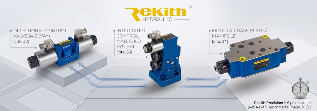
Directional Control: Manages the path of the fluid, directly dictating whether an actuator (like a cylinder) extends, retracts, or holds its position.
-
Pressure Control:Limits maximum system pressure (Relief Valves) or maintains a steady downstream pressure (Reducing Valves). Relief valves are your most critical safety components.For a step-by-step engineering walkthrough, see our guide: How to Adjust a Hydraulic Relief Valve.
-
Flow Control: Regulates the volume of fluid passing through per minute, which directly dictates the operational speed of the actuators.
Internal Mechanisms: Spool vs. Poppet
Spool Valves (Versatility)
Spool valves use a cylindrical sliding spool. They are ideal for complex multi-position control (like 4/3 directional valves) but always have some inherent internal leakage.
At Rekith, we use precision grinding and heat treatment to minimize this leakage for high-duty cycle industrial use.
Poppet Valves (Zero-Leakage)
Poppet valves use a cone or ball seated against a ring. When closed, they provide a near-perfect seal. These are preferred for safety-critical load-holding applications where “drifting” is not an option.
Manufacturer’s Selection Checklist: 5 Steps to Avoid Failure
To ensure system reliability and avoid premature component failure, we strongly recommend running through this critical engineering checklist before specifying any valve for your circuit:
-
Response Time: How fast does the valve shift from 0 to 100% flow? Match this to your actuator’s dynamic requirements.
-
Hysteresis (Crucial for Proportional Valves): What is the lag between the electrical input signal and the mechanical output? Minimizing this lag is the secret to high-precision control, which is why premium proportional valves rely on mirror-finish surface grinding.
-
Filtration Requirement: Does the valve require ISO 4406 18/16/13 cleanliness? Micro-contaminants are the leading cause of spool sticking in precision 2–6 micron clearances.
-
Fluid Compatibility: Are the internal seals (Viton, NBR, EPDM) chemically compatible with your specific operating hydraulic fluid?
-
Duty Cycle: Is the valve designed for light, intermittent use, or heavily engineered to withstand 24/7 continuous industrial production?
FAQ: Frequently Asked Questions
Q1: What are the three main types of hydraulic valves?
The three main types of hydraulic valves are Directional Control Valves (control path), Pressure Control Valves (limit or regulate pressure), and Flow Control Valves (regulate actuator speed). Each serves a specific role in safety and motion control.
Q2: How does a hydraulic relief valve work?
A hydraulic relief valve stays closed by spring force until system pressure exceeds its pre-set limit. Once the pressure threshold is reached, the valve opens, bypassing excess fluid back to the reservoir to protect the system from catastrophic overpressure.
Q3: What causes a hydraulic valve to stick?
Common causes include fluid contamination (particles jamming the micron clearances), thermal expansion (operating outside temperature limits), and lacquering (oil oxidation forming a sticky film on the spool).
Q4: Spool Valve vs. Poppet Valve: Which is better?
It depends on the application. Spool valves are better for continuous flow modulation and multi-directional control, while Poppet valves are superior for zero-leakage load holding and high-pressure safety applications.
Conclusion
Mastering the fundamentals of hydraulic valves is not just about understanding parts—it’s about mastering system predictability. By selecting a valve manufactured to rigorous geometric tolerances and material standards, you ensure a safer, more efficient fluid power system.
For custom manifold designs or expert valve selection, contact the Rekith Hydraulics engineering team.