Proportional valves sit between conventional on/off valves and closed-loop servo valves, and have become a common component in modern hydraulic systems.
Types of Proportional Valves
- Proportional pressure valves: These control the pressure in hydraulic systems, such as proportional relief valves and proportional reducing valves.

- Proportional flow valves: These control the flow in systems, like proportional flow control valves.

- Proportional directional valves: These control the movement direction and speed of hydraulic actuators.

📘 For engineers comparing control performance, see our
Proportional vs Directional Valve Technical Guide
Proportional vs Servo Valve Technical Guide
Characteristics of Electromagnetic Proportional Directional Valves
- Like regular directional valves, proportional solenoids directly drive the control spool in direct-acting proportional directional valves.
- Structurally, they resemble a three-position, four-way spring-centered standard directional valve.
- The spool has a large stroke similar to pilot-operated directional valves.
- The flow into and out of the actuator is constrained by two control orifices.
- Paired with an electronic controller, it can reliably achieve acceleration and deceleration, with adjustable ramp times set independently of the oil properties.
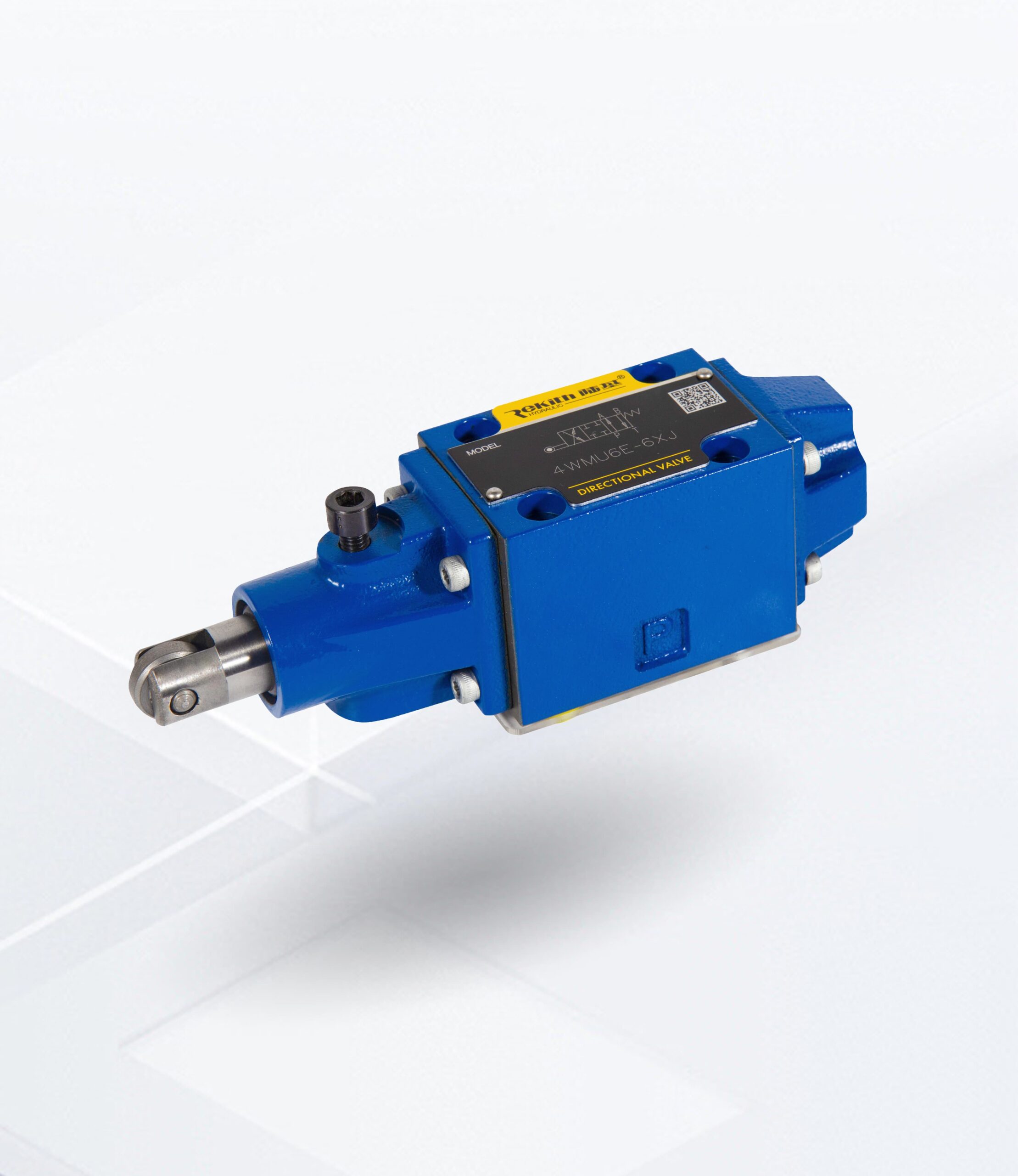
Proportional Directional Valve
The 4WRA(E) valve is a 4/2-way and 4/3-way proportional directional valve with direct operated and subplate mounting. It is actuated by proportional solenoids with central thread and detachable coil. The control of the solenoids can be achieved through external amplififier (4WRA) or internal amplififier (4WRAE).


Features
◆ Size 6 and 10
◆ Maximum working pressure 315 bar
◆ Maximum working flow 42 L/min (size 6)
75 L/min (size 10)
Electro-hydraulic Proportional Directional Valve
The 4WRKE valve is a two-stage proportional directional control valve. They control the size and direction of the flow. The main stage is position closed loop controlled so that the valve spool position is independent of the hydraulic force in larger flows.The valve consists of the pilot control valve (1),valve body (8), main valve spool (7), covers (5and 6), centering spring (4), inductive position sensor (9), and pressure reducing valve (3).If there is no input signal, the main valve spool (7) is held in the the central position by the centering spring (4). The two control chambers in the covers (5 and 6) are connected to the oil tank through the valve spool (2).The main valve spool (7) is connected to the corresponding electronic amplififier through the induction position sensor (9), the change of position of the main valve spool (7) as well as the change of the command value at the summing point of the amplififier result in a differential voltage.


Features
◆Size 10 to 32
◆ Maximum working pressure 350 bar
◆ Maximum working flow 1600 L/min
3-Way Proportional Pressure Reducing Valve
The 3DREP6 type 3-way pressure reducing valve is direct operated by proportional solenoid. It used to convert an electrical input signal into a proportional pressure output signal.The proportional solenoids are controllable wet pin DC solenoids with central thread and detachable coil. The solenoids are controlled by external amplififier (model 3DREP) or integrated amplififier (model 3DREPE).


Features
◆ Size 6
◆ Maximum working pressure 100 bar
◆ Maximum working flow 15 L/min
2-Way Proportional Flow Control Valve
The 2FRE…proportional flow control valves have a 2-way function They can control a corresponding flflow independent of pressure and temperature according to the provided electrical command value. The valve basically consists of valve body (1), proportional solenoid with inductive position transducer (2), measurement orififice (3), pressure compensator (4), and optional check valve (6).


Features
◆ Size 6
◆ Maximum working pressure 210bar
◆ Maximum working flow 25 L/min
Technical Application of Proportional Valves
Using car body assembly welding as an example:
Before a test drive, many automotive components have already experienced a “motion test” during the manufacturing process. The welding line assembles and welds the sheet metal parts stacked on the platform, involving several stations and more detailed processes.
All lifting platforms need to synchronize to reach the working position, i.e., the welding clamp area. The transportation of the metal sheet parts occurs during the deceleration stage, and the approach speed must not exceed 0.15 m/s, or the parts may not be accurately positioned. On the other hand, the lifting/lowering transport phase must move quickly to save time.
These process requirements are all achieved using hydraulic proportional control. After adopting the proportional control system, the maximum speed was significantly reduced. A throttle valve replaced the original acceleration/deceleration cam mechanism, a flow control valve handled speed regulation, and a directional valve controlled direction. If the traditional mechanical transmission method were still used, it would be unavoidable to experience hard impacts, low precision, and inflexibility. The system would become more complex and costly.
Hydraulic proportional control is especially suitable for systems with large inertia, high speed, and high acceleration, allowing balanced and reliable operation.
Common Issues and Troubleshooting with Proportional Valves
- The proportional solenoid does not work: This may be due to the aging of the connector components, poor contact, or the desoldering of the solenoid wires. In this case, a multimeter can be used for testing. If infinite resistance is detected, resolder the wires, repair the connector, and securely reconnect the plug. Broken wires or loose terminals between the proportional amplifier and the solenoid may also cause the solenoid to fail. Replace broken wires and reconnect them securely.
- Coil aging, coil burn-out, internal disconnection, or excessive temperature rise: Excessive temperature rise can reduce the output force of the proportional solenoid, causing it to fail. Check whether the input current is too high, if the coil insulation is faulty, or if the spool is stuck due to contaminants. Identify and eliminate the cause; replace coils for disconnection or burning issues.
- Improper valve installation: If the inlet and outlet ports are not correctly positioned in the manifold or if the surface of the manifold is rough, resulting in oil leakage, reinstall the valve correctly, treat the installation surface, and install sealing components.
- Unstable flow: Check the following aspects:
- Oil contamination: Contaminants in the hydraulic oil may block the throttle or spool, causing instability or jamming, affecting flow control.
- Oil temperature fluctuation: The viscosity of hydraulic oil changes with temperature, and excessive temperature variations can affect flow stability.
- Spool sticking or wear: Long-term use or contamination may cause the spool to wear or stick, preventing smooth movement and leading to unstable flow.
- Improper valve design (selection):Unstable flow in proportional valves can result from a combination of factors, including the condition of the hydraulic oil, temperature changes, spool wear, and electrical signal interference.
- Keep the hydraulic oil clean and at an appropriate temperature;
- Regularly maintain the proportional valve, cleaning and inspecting the spool;
- Ensure stable electrical control signals;
- Adjust controller parameters to match actual operating conditions;
- Optimize hydraulic system design to reduce external load and pressure fluctuations.
By systematically troubleshooting and optimizing, flow instability issues in proportional valves can be effectively resolved.
How to Select a Cost-Effective Proportional Valve
- Pressure rating selection: Pressure changes are achieved by altering the orifice diameter of the pilot stage. The selected proportional pressure valve’s rating should not be less than the system’s maximum working pressure, ideally 1-1.2 times, to achieve better resolution.
- Rated flow and size selection: To obtain a relatively flat flow-pressure curve and minimal set pressure, it is recommended that the rated flow of the proportional pressure valve be 1.2 to 2 times the system’s maximum flow. The corresponding size can then be found in the product catalog.
- Valve structure selection: Proportional valves with built-in feedback loops provide better stability and dynamic performance than those without. Valves with mechanical hydraulic feedback are simple, affordable, and reliable, with a hysteresis of less than 3% and repeatability within 1%. Proportional valves with electrical feedback can achieve hysteresis of less than 1.5% and repeatability within 0.5%.
- Accuracy: The static parameters of electro-hydraulic proportional valves, such as non-linearity, hysteresis, resolution, and repeatability, directly affect control accuracy. Select appropriately according to system accuracy requirements.
Development Trends of Proportional Valves
With the increasing automation of industries, the development trends of proportional valves mainly include:
- Digital control: More proportional valves are adopting digital control technology, achieving more precise control and diagnostic functions.
- Intelligence: Proportional valves, combined with sensor and network technologies, can achieve self-diagnosis and remote control.
- Energy efficiency: By optimizing valve body design and control algorithms, proportional valves can improve energy utilization while ensuring control accuracy.
Conclusion
Proportional valves are key components in hydraulic control systems, providing precise fluid control under complex working conditions. As control technology advances, the application prospects of proportional valves will become even broader.
FAQ: Proportional Valves
1. What is the difference between a proportional valve and a servo valve?
Servo valves generally offer higher dynamic response and accuracy, but they are more sensitive to oil contamination and are usually more expensive.
Proportional valves provide “good enough” performance for many industrial tasks with higher robustness and lower lifecycle cost.
2. Why does my proportional valve have unstable flow?
Common causes include contaminated oil blocking throttling edges, large temperature variations causing viscosity changes, worn or sticking spools, or incorrect valve selection and controller tuning.
Start with oil cleanliness and temperature, then check electrical signals and valve sizing.
3. How often should proportional valves be maintained?
There is no single rule, but regular checks of oil cleanliness, filter condition, connector integrity, and coil temperature are recommended as part of the system’s preventive maintenance plan.
In demanding systems, periodic functional tests and calibration may be necessary.
4. Can I replace a conventional valve with a proportional valve directly?
Not always. A proportional valve requires an appropriate amplifier or controller, suitable wiring, and sometimes a redesign of the circuit.
However, when correctly engineered, such upgrades can significantly improve performance, flexibility, and overall productivity.
About Rekith Hydraulics
Rekith Hydraulics is a specialized manufacturer of hydraulic valves and systems, supplying proportional directional valves, proportional pressure valves, flow control valves, cartridge valves, and logic valves for industrial machinery, mobile equipment, and energy applications.
With more than ten years of engineering experience, CNC-based production, and strict quality control, Rekith supports OEMs and system integrators worldwide with reliable products and application-level technical support
If you are planning or upgrading a hydraulic system and need help selecting proportional valves such as 4WRAE, 4WRKE, 3DREP6, or 2FRE types, our engineering team can provide calculation support and model recommendations based on your real operating conditions.